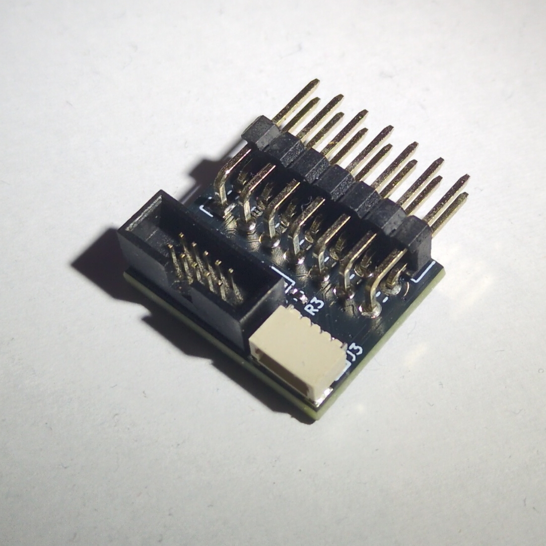
JTAG and QWIIC add-on board
This add-on board plugs into the CATT connector on the side of your Tanmatsu and provides a standard 10-pin JTAG interface for debugging the ESP32-P4 application processor as well as a QWIIC connector for connecting I2C devices and a LED for quick visual feedback.
Connectors
This section describes how the pins of the connectors on the board are connected to each other.
Pin |
CATT pin |
CATT name |
JTAG |
QWIIC |
LED |
Description |
|---|---|---|---|---|---|---|
1 |
14 |
+3.3v |
VTref |
3.3v output |
- |
3.3v output from Tanmatsu, used as reference voltage |
2 |
13 |
P4 reset |
RESET |
- |
- |
Reset input for the ESP32-P4 |
3 |
12 |
GND |
GND |
GND |
- |
Ground |
4 |
11 |
GND |
GND |
GND |
- |
Ground |
5 |
10 |
USER F |
MTDI |
- |
- |
JTAG data input |
6 |
9 |
USER E |
MTCK |
- |
- |
JTAG clock |
7 |
8 |
USER D |
MTDO |
- |
- |
JTAG data output |
8 |
7 |
USER C |
MTMS |
- |
- |
JTAG test mode select |
9 |
6 |
USER B |
DETECT |
- |
- |
Connected to ground by the programmer to enable JTAG mode |
10 |
5 |
USER A |
- |
- |
LED |
LED control, active low |
11 |
4 |
I2C SCL |
- |
SCL |
- |
I2C clock output |
12 |
3 |
I2C SDA |
- |
SDA |
- |
I2C data I/O |
13 |
2 |
GND |
GND |
GND |
- |
Ground |
14 |
1 |
+3.3v |
VTref |
+3.3v |
- |
3.3v output from Tanmatsu, used as reference voltage |
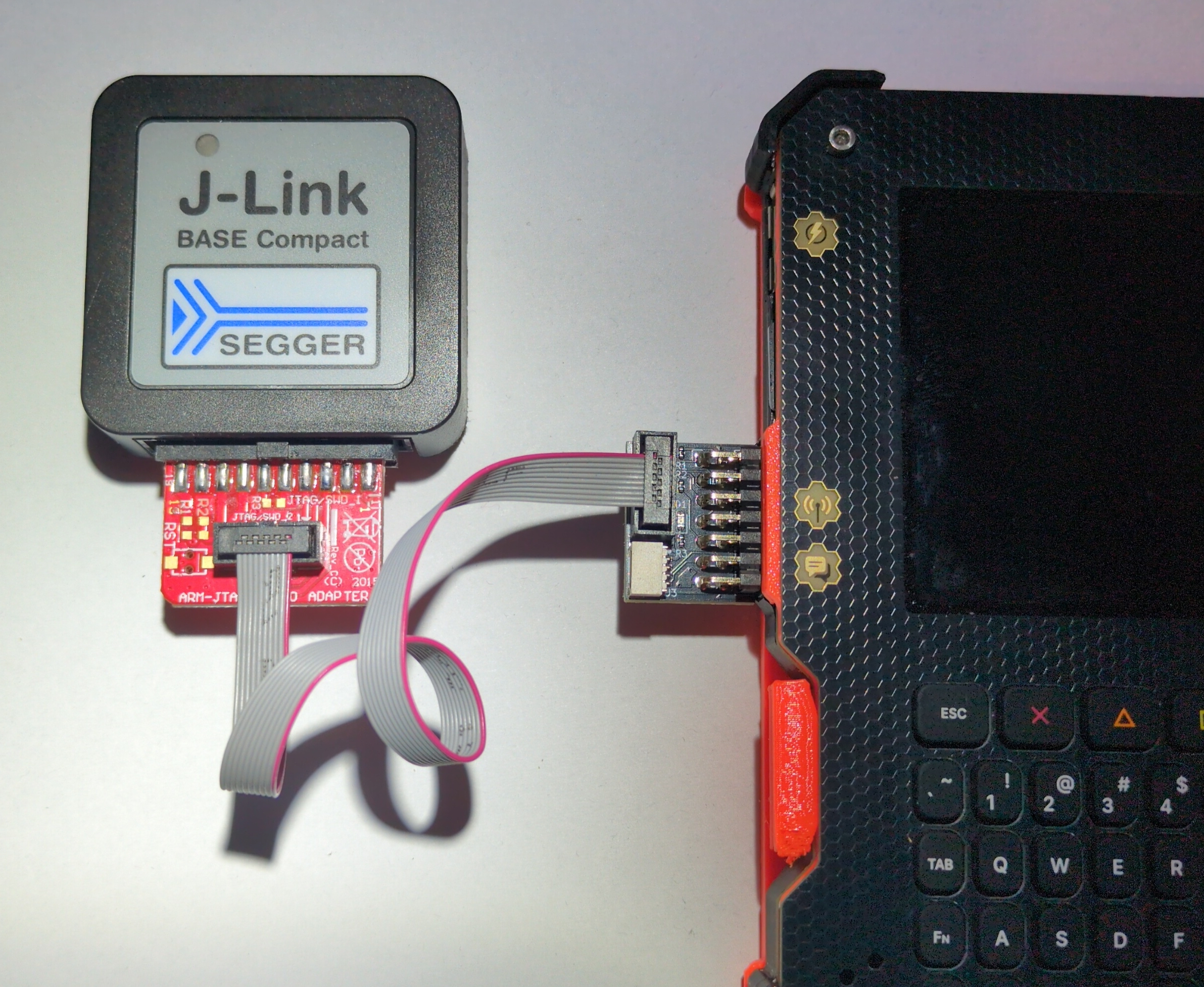
The JTAG header uses the standard 10-pin 1.27mm pitch “Cortex debug” style pinout.
Pin |
Description |
|---|---|
1 |
VTref |
2 |
MTMS |
3 |
GND |
4 |
MTCK |
5 |
GND |
6 |
MTDO |
7 |
- |
8 |
MTDI |
9 |
GND detect |
10 |
RESET |