External add-on port
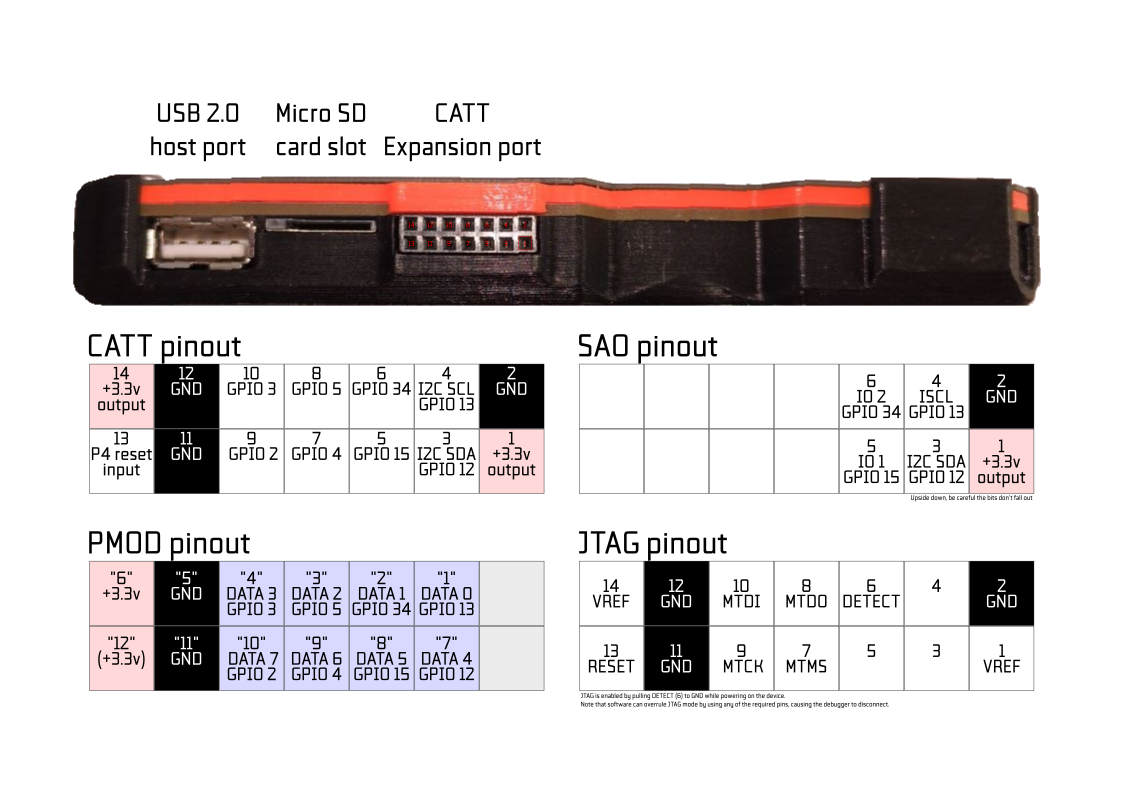
The external expansion port (CATT, for “Connect All The Things”) on Tanmatsu has been designed to be compatible with both PMOD and SAO add-on boards, in addition to it being a port that exposes 8 GPIOs and 3.3v power it can also be used as JTAG interface for the ESP32-P4.
Pinout
Pin 1 |
Pin 2 |
Pin 3 |
Pin 4 |
Pin 5 |
Pin 6 |
Pin 7 |
|
|---|---|---|---|---|---|---|---|
CATT |
+3.3v out |
GND |
I2C SDA |
I2C SCL |
IO 1 |
IO 2 |
IO 3 |
PMOD |
- |
- |
“7”: D4 |
“1”: D0 |
“8”: D5 |
“2”: D1 |
“9”: D6 |
SAO |
+3.3v out |
GND |
I2C SDA |
I2C SCL |
IO 1 |
IO 2 |
- |
JTAG |
+3.3v out |
GND |
- |
- |
- |
DETECT |
MTMS |
JTAG adapter |
+3.3v out |
GND |
I2C SDA |
I2C SCL |
LED |
DETECT |
MTMS |
ESP32-P4 GPIO |
- |
- |
12 |
13 |
15 |
34 |
4 |
Pin 8 |
Pin 9 |
Pin 10 |
Pin 11 |
Pin 12 |
Pin 13 |
Pin 14 |
|
|---|---|---|---|---|---|---|---|
CATT |
IO 4 |
IO 5 |
IO 6 |
GND |
GND |
P4 reset |
+3.3v out |
PMOD |
“3”: D5 |
“10”: D7 |
“4”: D3 |
GND |
GND |
“+3.3v” |
+3.3v out |
SAO |
- |
- |
- |
- |
- |
- |
- |
JTAG |
MTDO |
MTCK |
MTDI |
GND |
GND |
P4 reset |
+3.3v out |
JTAG adapter |
MTDO |
MTCK |
MTDI |
GND |
GND |
P4 reset |
+3.3v out |
ESP32-P4 GPIO |
5 |
2 |
3 |
- |
- |
- |
- |
Limitations, warnings and hints
Total for all 3.3v outputs must not exceed 1A of current. It is generally adviced to stay well below this figure.
To switch the JTAG interface from the USB serial/debug peripheral over to the CATT port pins pull “DETECT” low. This pin has a pull-up resistor in place.
Software can overrule the JTAG interface pins by configuring them as GPIO, this will cause the debugger to disconnect.
If you want to use JTAG via the USB-C port you will need to set the JTAG source manually in software if pin 6 (GPIO34) is being pulled low by an add-on board
The JTAG adapter we sell includes a LED and a QWIIC port next to the standard 10-pin JTAG connector.
The “P4 reset” input can safely be ignored or connected to the 3.3v rail if not in use.
You can short jumper JP1 to connect pin 13 to the +3.3v rail, disabling the reset signal on the CATT port.
Pins 3 and 4 (I2C) will show some activity during startup of the launcher firmware, to detect add-on boards with an identification EEPROM.